Soil Erosion:Channel Sediment Transport Formulation
The present version of GSSHA employs the unit stream power method of Yang’s (1973) for routing sand-size total-load in stream channels. Unit stream power is defined as the product of the average flow velocity, U, and the channel slope So. The rate of work done per unit weight of water in transporting sediment is assumed directly related to the rate of work available per unit weight of water. Thus, the total sediment concentration or total bed-material load must be directly related to the unit stream power. The following relation gives the basic concept of Yang’s (1973) method:
where: Cs is the total concentration of sand-size sediment particles in motion, USo is unit stream power (L/T), U* is the shear velocity (L/T), ν = kinematic viscosity of the sediment-water mixture (L/T2), w = fall velocity of the sediment (L/T), d = particle diameter (L). With some mathematical and statistical manipulations with Buckingham’s π theorem, Yang (1973) derived an energy-based equation to estimate the total sand-size sediment concentration in the channel.
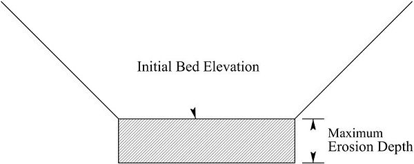
Only particles sizes larger than a user specified value for sand are transported in this manner. Smaller particles are assumed to be suspended, and not bedload, and are transported with the advection dispersion equation. The bed is assumed to be mobile, and the banks fixed. The bed can agrade or degrade to a user-specified maximum allowable depth(Figure 14).
Either trapezoidal or natural cross sections can be used. Trapezoidal channels degrade vertically into the crosshatched area in the Figure 14. Degradation continues and bed load is transported at the rate calculated with the Yang (1973) method until the maximum degradation is reached. During degradation the initial bed width is maintained and degradation is uniform across the width of the bed. If the channel aggrades, the trapezoidal cross-section is filled. If a channel link has aggraded, and then degrades, the degradation will occur uniformly over the bottom of the trapezoid until the original bed elevation is restored. Further degradation occurs vertically downward from the initial trapezoid bottom-width. If a channel, degraded below the original bed elevation begins to aggrade, sediment will accumulate uniformly in the rectangular degraded area below the original bed elevation. Once the bed aggrades beyond the original bed elevation, the entire width of the trapezoid is filled. Natural channels follow a similar pattern of agradation and degradation. The change in channel bed elevations is tracked during the simulation of the model and the final computed bed elevations are output in a file called "new_bed_elevations.txt". These new computed bed elevations are not used in the computations during the simulation unless you specify the "ADJUST_CHANNEL_BED", in which case the bed will be dynamically adjusted during the simulation, affecting all channel computations as the simulation proceeds.
In the channels size particles smaller than the user specified value of sand are assumed to be in suspension, and are transported as wash load. This treatment implies that the flow is turbulent, and the travel time to the outlet of the catchment is short compared to the settling time, such that particles do not settle in the channel network. This assumption, combined with no bank erosion, results in the channels being neither a source nor sink of fines. Routing of suspended fines is a natural extension of the explicit diffusive-wave channel routing method. Suspended fine sediments are routed as concentrations. The concentration changes as a function of gradients in both concentration and velocity.
GSSHA User's Manual
- 10 Soil Erosion
- 10.1 Overland Erosion Formulation
- 10.2 Channel Sediment Transport Formulation
- 10.3 Sediment in Lake
- 10.4 Applicability of the Sediment Routing Methods
- 10.5 Simulations with Soil Erosion
