Tutorials:5 Stream Flow
This tutorial is compatible with:
- WMS Version 8.1 and later
- GSSHA Version 3.0b and later
Disclaimer: GSSHA tutorial exercises do not represent real world conditions
Creating GSSHA™ Stream Arcs
At present the GSSHA™ streams are generic and have no defined geometry. To specify a stream size, we will need to supply dimensions for each stream arc in the Judy’s Branch basin. If you are beginning at this tutorial:
- In the 2D Grid module
 select GSSHA™ | Open Project File.
 - Browse to the Finished_tutorial\land_use folder and select the land_use.prj file and click Open.
- In the Project Explorer select the GSSHA Coverage.
- Select the map module of WMS
 .
. - Click on the “Select Branch” tool
 .
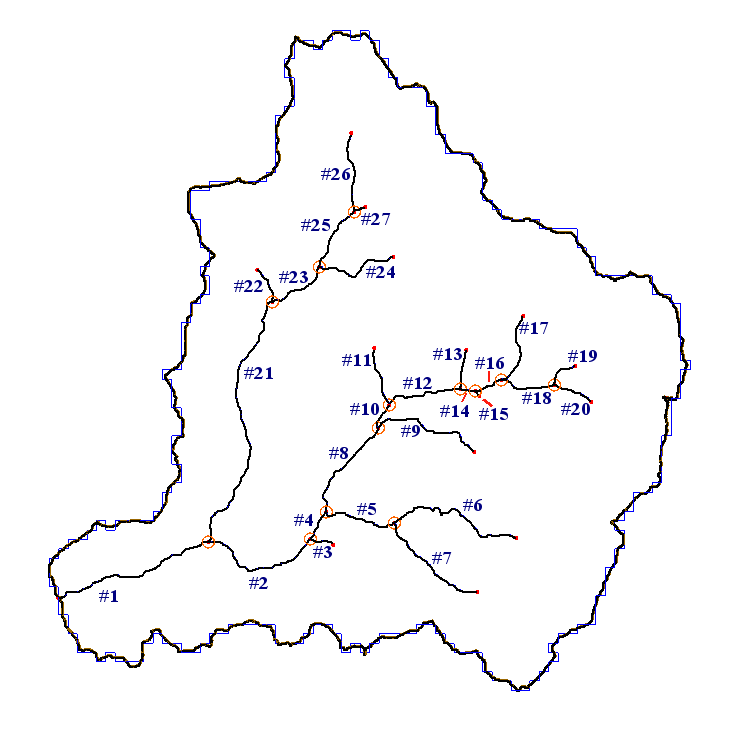
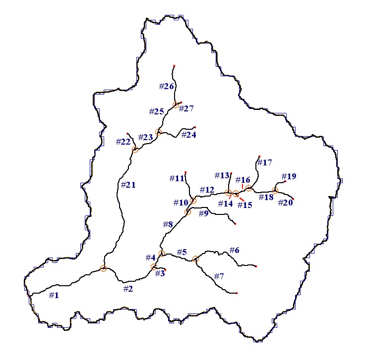
. - With this tool selected, click on the stream segment labeled “#1” on the following figure to select all streams.
- Select Feature Objects | Attributes…
- Toggle on “Trapezoidal Channel” which allows you to define stream geometry for the stream arcs.
- Fill out the edit fields according to the following table.
- Click OK.
- Switch to the “Select Arc” tool
 to modify streams one segment at a time.
 - Double-click stream segment “#2” as shown in the previous figure.
- Enter the values for depth, width, roughness and slope as shown in the following table.
- Repeat steps 11 and 12 for stream arcs 3 through 27.
In WMS, the tools for working with 2D grid data are in the 2D Grid module. The tools for working with the stream data are in the Map module. In order to set up the stream model four things must be done. The stream arcs must be set to a GSSHA™ stream arc type, the stream thalwegs refined, the stream geometry defined, and the channel routing job control item set.
Because of the way we set up the GSSHA™ basin, we have in the GSSHA™ coverage a set of stream arcs. These stream arcs, however, are currently set to be generic stream arcs instead of a type that can be used in GSSHA™.
|
Now all the stream arcs in the basin are defined as trapezoidal channels, and have identical geometries. There are two types of channels that GSSHA™ recognizes, trapezoidal and break-point. It would be nice if we could add some variation to our streams in order to represent the streams narrowing upstream. To do this we will change the dimensions of the upstream arcs.
|
The stream arcs now have defined geometries and are ready to be smoothed.
Smoothing the Stream Arcs
Now that the geometry for each stream arc has been defined, it is important to ensure that each arc is flowing downhill. Due to inaccuracies in the DEM data, stream arcs will occasionally flow uphill, which causes digital dams and other problems. To alleviate this dilemma, we will look at the stream profiles and modify the point elevations until each arc is flowing downhill. First, however, we need to redistribute the vertices on the arcs to a more reasonable spacing.
- Select the map module
 .
. - If the Model combo box on the X, Y, Z edit bar is not set to GSSHA™, change it to GSSHA™.
- Click on the Select Branch tool
 .
. - Click on the stream segment labeled “#1” on the figure below to select all streams.
- Select the Feature Objects | Redistribute.
- Type 90 in the box next to Spacing and click OK.
- Pick the Select Arc tool
 .
. - Select arc # 1 as shown on the figure above, and while holding down the shift key, select stream arcs “#2” and “#4”
- With these streams selected select GSSHA™ | Smooth Stream Arcs…
- In the pop-up window, click on the “Interpolate stream elevations” buttons as many times as needed to generate a smooth stream segment with no uphill flow, then click OK.
- If uphill flow cannot be eliminated in this manner, you can edit individual points by selecting the “select a point” tool
 , then dragging the point to a new position or editing the value in the box next to “Stream elevation.” Be especially careful to make sure the nodes next to the outlet are not adverse.
 - Click and drag around a point in the display to zoom in on individual points and modify them.
- You can also use the scroll bars in the plot window to move along the zoomed stream segment.
- Once the stream segment you have selected is smooth, select a new stream segment or combination of segments to smooth.
- Repeat the smoothing process outlined in steps 8 through 14 until all arcs in the basin are smooth.
- In the 2D Grid Module
 Select GSSHA™ | Job Control….
 - Under Channel Routing toggle on Diffusive Wave.
- Select the Output Control button.
- Under Link / Node data sets toggle Channel depth and Channel flow on.
- Click OK.
- Click OK.
In the Smooth GSSHA™ Streams dialog you will see a profile of the arcs you have selected. Notice that while the segment has a general downward trend, in some places the streambed is significantly adverse. While GSSHA™ is able to handle adverse slopes, it is not desirable that adverse slopes should be in the model where they do not exist in life. We will mitigate this problem by making slight changes to the vertex and node elevations along the segment.
Your streams are now ready for use in the GSSHA™ model.
There is one last step before saving the model. The stream routing option must be turned on in the Job Control dialog.
Save the model and run it.
GSSHA Tutorials
GSSHA Tutorial Download Website

