Surface Water Routing:Embankments
Embankments, dikes, levees, or whatever you want to call them, can be modeled in GSSHA as a sequence of flow barriers between cells. Overtopping flow can be modeled as broad-crested weir flow over the flow barrier. Two files may be specified, the dike mask and the low spot file. The dike mask is necessary for modeling the embankments, but the low spot file is only used if you want overtopping flow. If no low spot file is specified then the dikes are assumed to never overtop. Rating curves can be used to pass water through an embankment. Embankments can be used to control lake boundaries and separate lakes and keep them from joining during the simulation, which is not permitted in GSSHA. Rating curves can also be used to pass water between lakes that are separated by an embankment.
Project File Cards
The dike mask is specified by using either the card
DIKE_MASK "filename.dik"
or the card
EMBANKMENTS "filename.dik"
Either card will work, and they both have the same function.
The low spot file is specified using the following card:
LOWSPOT_FILE "filename.lsp"
Dike Mask
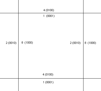
In GSSHA, flow is modeled as occuring from cell to cell so the dikes must operate between cells (on the cell faces) to block the flow of water. The first step in modeling the dikes is to map the actual location of the dikes to the nearest cell edges. Once that is accomplished, each cell gets a code that tells what cell edges are not allowed flow. This code is simply a binary code, where 1 (0001 in binary) is the top face (north,) 2 (0010 in binary) is the right face (east,) 4 (0100 in binary) is the lower face (south,) and 8 (1000 in binary) is the left face (west.) The code in each cell is the sum of the codes for the edges. You should remember that what is a left face in one cell is the right face in the adjacent cell, etc. The dike mask file is simply a GRASS ASCII grid, similar to the index maps, that has the code for each cell. Usually most cells will be zero. All values are in decimal.
The following figure shows the codes for each face.

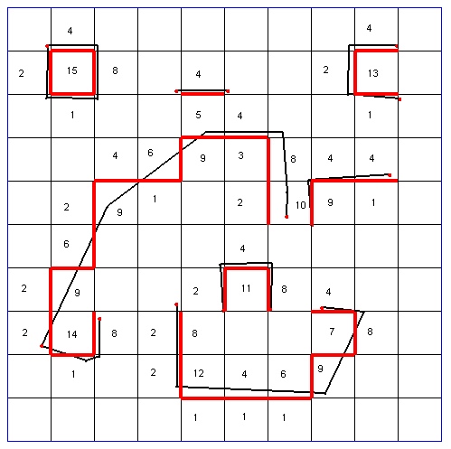
The following figure shows an example of the codes for all possible configurations of dike edges. The thicker black lines are the dike arcs, the thick red lines the edges over which flow will not pass, and the numbers are the codes for the cells. All zeros are not shown for clarity.

Low Spot File
The low spot file describes which faces the flow can pass over, at what elevation, and provides all the necessary paramters. The low spots have a code, the same binary code above, describing which face they apply to, and they also have a percent of the edge that flow can pass over. This allows for situations where the dike/embankment/etc. changes elevation over the cell, such as in a vertical curve used over a culvert.
The low spot file is set up with all the parameters describing a low spot placed horizontally on one line.
An example of the low spot file follows. The first line is the file header, the second line is a text line for help in reading the file. Each low spot begins the line with the card "SPOT" followed by the row (cell I,) column (cell J,) the side code (same as above, but only one side at a time,) the cell edge fraction (0.0 to 1.0,) and the elevation of the crest of the low spot.
LOWSPOT FILE
#     ROW  COL  SIDE FRAC   ELEV
SPOT  9    1    1    0.2500 27.600
SPOT  9    2    1    0.5000 27.200
SPOT  9    2    1    0.5000 27.400
SPOT  9    3    1    0.2500 27.600
...
The equation used to model flow is an unsubmerged broad-crested weir equation:
![]()
where ![]() is defined as the depth of water above the crest.
is defined as the depth of water above the crest.
GSSHA User's Manual
- 5 Surface Water Routing
- 5.1 Channel Routing
- 5.2 Overland Flow Routing
- 5.3 Channel Boundary Conditions
- 5.4 Overland Boundary Conditions
- 5.5 Embankments
- 5.6 Overland/Channel Interaction
- 5.7 Introducing Discharge/Constituent Hydrographs
- 5.8 Overland Routing with Snow
- 5.9 Overland Routing with BMPs